Running Game Boy Games On STM32 MCUs Is Peanuts

Using a STM32F429 Discovery board [Jan Zwiener] put together a Game Boy-compatible system called STM32Boy. It is based around the Peanut-GB Game Boy emulator core, which is a pretty nifty and fast single-header GB emulator library in C99. Considering that the average 32-bit MCU these days is significantly faster than the ~4 MHz  8-bit Sharp SM83 (Intel 8080/Zilog Z80 hybrid) in the original Game Boy it’s probably no surprise that the STM32F429 (up to 180 MHz) can emulate this 8-bit SoC just fine.

Since Peanut-GB is a library, the developer using it is expected to provide their own routines to read and write RAM and ROM and to handle errors. Optional are the line drawing, audio read/write and serial Tx/Rx functions, with the library providing reset and a host of other utility functions. Audio functionality is provided externally, such as using the provided MiniGB APU. Although fast, it comes with a range of caveats that limit compatibility and accuracy.

For STM32Boy, [Jan] uses the LCD screen that’s on the STM32 development board to render the screen on, along with a Game Boy skin. The LCD’s touch feature is then used for the controls, as can be elucidated from the main source file. Of note is that the target GB ROM is directly compiled into the firmware image rather than provided via an external SD card. This involves using the xxd tool to create a hex version of the ROM image that can be included. Not a bad way to get a PoC up and running, but we imagine that if you want to create a more usable GB-like system it should at least be able to play more than one game without having to reflash the MCU.

Doing 1080p Video, Sort Of, On The STM32 Microcontroller

When you think 1080p video, you probably don’t think STM32 microcontroller. And yet! [Gabriel Cséfalvay] has pulled off just that through the creative use of on-chip peripherals. Sort of.

The build is based around the STM32L4P5—far from the hottest chip in the world. Depending on the exact part you pick, it offers 512 KB or 1 Mbyte of flash memory, 320 KB of SRAM, and runs at 120 MHz. Not bad, but not stellar.

Still, [Gabriel] was able to push 1080p at a sort of half resolution. Basically, the chip is generating a 1080p widescreen RGB VGA signal. However, to get around the limited RAM of the chip, [Gabriel] had to implement a hack—basically, every pixel is RAM rendered as 2×2 pixels to make up the full-sized display. At this stage, true 1080p looks achievable, but it’ll be a further challenge to properly fit it into memory.

Output hardware is minimal. One pin puts out the HSYNC signal, another handles VSYNC. The same pixel data is clocked out over R, G, and B signals, making all the pixels either white or black. Clocking out the data is handled by a nifty combination of the onboard DMA functionality and the OCTOSPI hardware. This enables the chip to hit the necessary data rate to generate such a high-resolution display.

There’s more work to be done, but it’s neat to see [Gabriel] get even this far with such limited hardware. We’ve seen others theorize similar feats on chips like the RP2040 in the Pi Pico, too. Video after the break.

Continue reading “Doing 1080p Video, Sort Of, On The STM32 Microcontroller”

screenshot of the code defining a hid descriptor by using essentially macros for common descriptor types

Coupling STM32 And Linux? Consider HID Over I2C

If you’re pairing a tiny Linux computer to a few peripherals — perhaps you’re building a reasonably custom Pi-powered device — it’s rightfully tempting to use something like an STM32 for all your low-level tasks, from power management to reading keyboard events.

Now, in case you were wondering how to tie the two together, consider HID over I2C, it’s a standardized protocol with wide software and peripheral support, easily implementable and low-power. What’s more, [benedekkupper] gives you an example STM32 project with a detailed explanation on how you too can benefit from the protocol.

There are several cool things about this project. For a start, its code is generic enough that it will port across the entire STM32 lineup nicely. Just change the pin definitions as needed, compile it, flash it onto your devboard and experiment away. Need to change the descriptors? The hid-rdf library used lets you define a custom descriptor super easily, none of that building a descriptor from scratch stuff, and it even does compile-time verification of the descriptor!

The project has been tested with a Raspberry Pi 400, and [benedekkupper] links a tutorial on quickly adding your I2C-HID device on an Linux platform; all you need is DeviceTree support. Wondering what’s possible with HID? We’ve seen hackers play with HID aplenty here, and hacking on the HID standard isn’t just for building keyboards. It can let you automate your smartphone, reuse a laptop touchpad or even a sizeable Wacom input surface, liberate extra buttons on gamepads, or build your own touchscreen display.

A solar-powered decibel meter the size of a business card.

2024 Business Card Challenge: NoiseCard Judges The Sound Around You

Let’s face it: even with the rise of the electric car, the world is a noisy place. And it seems like it has only gotten worse in recent years. But how can we easily quantify the noise around us and know whether it is considered an unhealthy decibel level?

That is where the NoiseCard comes in. This solar-powered solution can go anywhere from the regrettable open office plan to the busy street, thanks to a couple of 330 µF capacitors. It’s based on the low-power STM32G031J6 and uses a MEMS microphone to pick up sound from the back of the card, which the code is optimized for. Meanwhile, the LEDs on the front indicate the ambient noise level, ranging from a quiet 40 dB and under to an ear-splitting 105 dB or greater.

When it comes to building something the size of a business card, every component is under scrutiny for size and usefulness. So even the LEDs are optimized for brightness and low power consumption. Be sure to check it out in action after the break in various environments.

Continue reading “2024 Business Card Challenge: NoiseCard Judges The Sound Around You”

Hands On: Inkplate 6 MOTION

Over the last several years, DIY projects utilizing e-paper displays have become more common. While saying the technology is now cheap might be overstating the situation a bit, the prices on at least small e-paper panels have certainly become far more reasonable for the hobbyist. Pair one of them with a modern microcontroller such as the RP2040 or ESP32, sprinkle in a few open source libraries, and you’re well on the way to creating an energy-efficient smart display for your home or office.

But therein lies the problem. There’s still a decent amount of leg work involved in getting the hardware wired up and talking to each other. Putting the e-paper display and MCU together is often only half the battle — depending on your plans, you’ll probably want to add a few sensors to the mix, or perhaps some RGB status LEDs. An onboard battery charger and real-time clock would be nice as well. Pretty soon, your homebrew e-paper gadget is starting to look remarkably like the bottom of your junk bin.

For those after a more integrated solution, the folks at Soldered Electronics have offered up a line of premium open source hardware development boards that combine various styles of e-paper panels (touch, color, lighted, etc) with a microcontroller, an array of sensors, and pretty much every other feature they could think of. To top it off, they put in the effort to produce fantastic documentation, easy to use libraries, and free support software such as an online GUI builder and image converter.

We’ve reviewed a number of previous Inkplate boards, and always came away very impressed by the attention to detail from Soldered Electronics. When they asked if we’d be interested in taking a look at a prototype for their new 6 MOTION board, we were eager to see what this new variant brings to the table. Since both the software and hardware are still pre-production, we won’t call this a review, but it should give you a good idea of what to expect when the final units start shipping out in October.

Continue reading “Hands On: Inkplate 6 MOTION”

A System Board For The 8008

Intel processors, at least for PCs, are ubiquitous and have been for decades. Even beyond the chips specifically built by Intel, other companies have used their instruction set to build chips, including AMD and VIA, for nearly as long. They’re so common the shorthand “x86” is used for most of these processors, after Intel’s convention of naming their processors with an “-86” suffix since the 1970s. Not all of their processors share this convention, though, but you’ll have to go even further back in time to find one. [Mark] has brought one into the modern age and is showing off his system board for this 8008 processor.

The 8008 predates any x86 processor by about six years and was among the first mass-produced 8-bit processors even before the well-known 8080. The expansion from four bits to eight was massive for the time and allowed a much wider range of applications for embedded systems and early personal computers. [Mark] goes into some of the details for programming these antique processors before demonstrating his system board. It gets power from a USB-C connection and uses a set of regulators and level shifters to make sure the voltages all match. Support for all the functions the 8008 needs is courtesy of an STM32. That includes the system memory.

For those looking to develop something like this, [Mark] has also added his development tools to a separate GitHub page. Although it’s always a good idea for those interested in computer science to take a look at old processors like these, it’s not always the easiest path to get original hardware like this, which also carries the risk of letting smoke out of delicate components. A much easier route is to spin up an emulator like an 8086 IBM PC emulator on an ESP32. Want to see inside this old chip? Have a look.

Continue reading “A System Board For The 8008”

Multiply Your Multimeter With Relays And USB

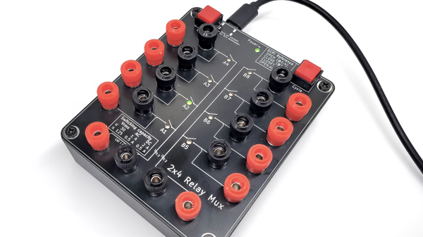
Multimeters are a bit like potato chips: you can’t have just one. But they’re a lot more expensive than potato chips, especially the good ones, and while it’s tempting to just go get another one when you need to make multiple measurements, sometimes it’s not practical. That’s why something like this 2×4 relay-based multiplexer might be a handy addition to your bench

In this age of electronics plenty, you’d think that a simple USB relay board would be easy enough to lay hands on. But [Petteri Aimonen] had enough trouble finding a decent one that it became easier to just roll one up from scratch. His goal was to switch both the positive and negative test leads from up to four instruments to a common set of outputs, and to have two independent switching banks, for those times when four-lead measurements are needed. The choice of relay was important; [Petteri] settled on a Panasonic DPDT signal relay with low wetting current contacts and a low-current coil. The coils are driven by a TBD62783A 8-channel driver chip, while an STM32 takes care of USB duties.

The mechanical design of this multiplexer is just as slick as the electrical. [Petteri] designed the PCB to act as the cover for a standard Hammond project box, so all the traces and SMD components are mounted on the back. That just leaves the forest of banana-plug binding posts on the front, along with a couple of pushbuttons for manual input switching and nicely silkscreened labels. The multiplexer is controlled over USB using the SCPI protocol, which happily includes an instrument class for signal switchers.

We think the fit and finish on this one is fantastic, as is usual with one of [Petteri]’s builds. You’ll probably recall his calibrated current reference or his snazzy differential probe.