Don’t Let The Baluns Float Over Your Head

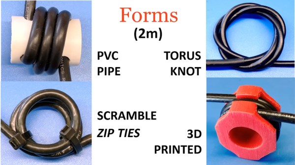
Most ham radio operators will build an antenna of some sort when they first start listening or transmitting, whether it’s a simple dipole, a beam antenna like a Yagi, or even just a random wire vertical antenna. All of these will need to be connected feedline of some sort, and in the likely event you reach for some 50-ohm coax cable you’ll also need a balun to reduce noise or unwanted radiation. Don’t be afraid of extra expenses when getting into this hobby, though, as [W6NBC] demonstrates how to construct an “ugly balun” out of the coax wire itself (PDF).

The main purpose of a balun, a contraction of “balanced-unbalanced” is to convert an unbalanced transmission line to a balanced one. However, as [W6NBC] explains, this explanation obscures much of what baluns are actually doing. In reality, they take a three-wire system (the coax) and convert it to a two-wire system (the antenna), which keeps all of the electrical noise and current on the shield wire of the coax from interfering with the desirable RF on the interior of the coax.

This might seem somewhat confusing on the surface, as coax wires only have a center conductor and a shield wire, but thanks to the skin effect which drives currents to the outside of the conductor, the shield wire effectively becomes two conductors when taking into account its inner and outer surfaces. At these high frequencies the balun is acting as a choke which keeps these two high-frequency conductors separate from one another, and keeps all the noise on the outside of the shield wire and out of the transmitter or receiver.

Granted, the world of high-frequency radio circuits can get quite complex and counter-intuitive and, as we’ve shown before, can behave quite unexpectedly when compared to DC or even mains-frequency AC. But a proper understanding of baluns and other types of transformers and the ways they interact with RF can be a powerful tool to have. We’eve even seen other hams use specialty transformers like these to make antennas out of random lengths and shapes of wire.

Continue reading “Don’t Let The Baluns Float Over Your Head”

Weird World Of Microwaves Hack Chat

Join us on Wednesday, December 18 at noon Pacific for the Weird World of Microwaves Hack Chat with Shahriar Shahramian! We’ve been following him on The Signal Path for years and are excited to pick his brain on what is often considered one of the dark arts of electronics.

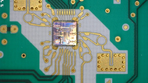
No matter how much you learn about electronics, there always seems to be another door to open. You think you know a thing or two once you learn about basic circuits, and then you discover RF circuits. Things start to get a little strange there, and stranger still as the wavelengths decrease and you start getting into the microwave bands. That’s where you see feed lines become waveguides, PCB traces act as components, and antennas that look more like musical instruments.

Shahriar is no stranger to this land. He’s been studying millimeter-wave systems for decades, and his day job is researching millimeter-wave ASICs for Nokia Bell Labs in New Jersey, the birthplace of the transistor. In his spare time, Shahriar runs The Signal Path, a popular blog and YouTube channel where he dives tear-downs, explanations, and repairs of incredibly sophisticated and often outrageously expensive equipment.

We’ll be sitting down with Shahriar this week for the last Hack Chat of 2019 with a peek inside his weird, wonderful world of microwaves. Join us with your questions about RF systems, microwaves in the communication industry, and perhaps even how he manages to find the gear featured on his channel.

join-hack-chatOur Hack Chats are live community events in the Hackaday.io Hack Chat group messaging. This week we’ll be sitting down on Wednesday, December 18 at 12:00 PM Pacific time. If time zones have got you down, we have a handy time zone converter.

Click that speech bubble to the right, and you’ll be taken directly to the Hack Chat group on Hackaday.io. You don’t have to wait until Wednesday; join whenever you want and you can see what the community is talking about.

Everything You Didn’t Know You Were Missing About Bias Tees

Do you need a bias tee? If you want to put a DC voltage on top of an RF signal, chances are that you do. But what exactly are bias tees, and how do they work?

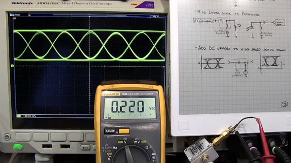
If that’s your question, [W2AEW] has an answer for you with this informative video on the basics of bias tees. A bias tee allows a DC bias to be laid over an RF signal, and while that sounds like a simple job, theory and practice often deviate in the RF world. The simplest bias tee would have a capacitor in series with the RF input and output to pass AC but block DC from getting out the input, and a DC input with a series inductance to prevent RF from getting into the DC circuit. Practical circuits are slightly more complicated, and [W2AEW] covers all you need to know about how real-world bias tees are engineered. He also gives some use cases for bias tees, from sending DC signals up a feed line to control an antenna tuner or rotator to adding a DC bias to a high-speed serial line.

It’s an interesting circuit, and we learned a lot, which is par for the course with [W2AEW]’s videos. Check out some of his other offerings, like a practical guide to the mysteries of Smith charts, or his visualization of how standing waves work.

Continue reading “Everything You Didn’t Know You Were Missing About Bias Tees”