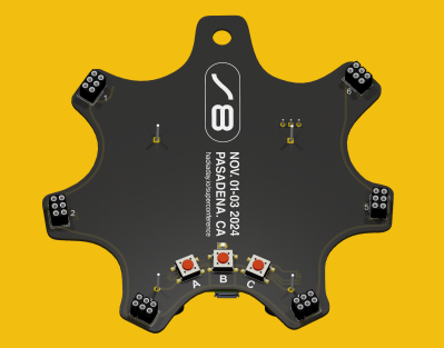
Supercon 2024 Flower SAO Badge Redrawing In KiCad

Out of curiosity, I redrew the Supercon Vectorscope badge schematics in KiCad last year. As you might suspect, going from PCB to schematic is opposite to the normal design flow of KiCad and most other PCB design tools. As a result, the schematics and PCB of the Vectorscope project were not really linked. I decided to try it again this year, but with the added goal of making a complete KiCad project. As usual, [Voja] provided a well drawn schematic diagram in PDF and CorelDRAW formats, and a PCB design using Altium’s Circuit Maker format (CSPcbDoc file). And for reference, this year I’m using KiCad v8 versus v7 last year.

Importing into KiCad

This went smoothly. KiCad imports Altium files, as I discovered last year. Converting the graphic lines to traces was easier than before, since the graphical lines are deleted in the conversion process. There was a file organizational quirk, however. I made a new, empty project and imported the Circuit Maker PCB file. It wasn’t obvious at first, but the importing action didn’t make use the new project I had just made. Instead, it created a completely new project in the directory holding the imported Circuit Maker file. This caused a lot of head scratching when I was editing the symbol and footprint library table files, and couldn’t figure out why my edits weren’t being seen by KiCad.  I’m not sure what the logic of this is, was an easy fix once you know what’s going on. I simply copied everything from the imported project and pasted it in my new, empty project.

While hardly necessary for this design, you can also import graphics into a KiCad schematic in a similar manner to the PCB editor. First, convert the CorelDRAW file into DXF or SVG — I used InkScape to make an SVG. Next do Import -> Graphics in the Kicad schematic editor. However, you immediately realize that, unlike the PCB editor, the schematic editor doesn’t have any concept of drawing layers. As a work around, you can instead import graphics into a new symbol, and place this symbol on a blank page. I’m not sure how helpful this would be in tracing out schematics in a real world scenario, since I just drew mine from scratch. But it’s worth trying if you have complex schematics.

Note: this didn’t work perfectly, however. For some reason, the text doesn’t survive being imported into KiCad. I attribute this to my poor InkScape skills rather than a shortcoming in KiCad or CorelDRAW. Despite having no text, I put this symbol on its own page in sheet two of the schematic, just for reference to see how it can be done.

Just like last year, the footprints in the Circuit Maker PCB file were imported into KiCad in a seemingly random manner. Some footprints import as expected. Others are imported such that each individual pad is a standalone footprint. This didn’t cause me any problems, since I made all new footprints by modifying standard KiCad ones. But if you wanted to save such a footprint-per-pad part into a single KiCad footprint, it would take a bit more effort to get right.

Recreating Schematics and Parts

After redrawing the schematics, I focused on getting the part footprints sorted out. I did them methodically one by one. The process went as follows for each part:

  • Start with the equivalent footprint from a KiCad library
  • Duplicate it into a local project library
  • Add the text SAO to the footprint name to avoid confusion.
  • Position and align the part on the PCB atop the imported footprint
  • Note and adjust for any differences — pad size and/or shape, etc.
  • Update the part in the project library
  • Attach it to the schematic symbols in the usual manner.
  • Delete the imported original footprint (can be  tricky to select)

Some parts were more interesting than others. For example, the six SAO connectors are placed at various non-obvious angles around the perimeter. I see that [Voja] slipped up once — the angle between connectors 4 and 5 is at a definitely non-oddball angle of 60 degrees.

SAO Angle Difference
#1   326  102  6->1
#2     8   42  1->2
#3    61   53  2->3
#4   118   57  3->4
#5   178   60  4->5
#6   224   46  5->6

With all this complete, the PCB artwork consists of all new footprints but uses the original traces. I needed to tweak a few traces here and there, but hopefully without detracting too much from [Voja]’s style. Speaking of style, for those interested in giving that free-hand look to hand-routed tracks in KiCad, check the options in the Interactive Router Settings menu. Choose the Highlight collisions / Free angle mode and set the PCB grid to a very small value. Free sketch away.

Glitches

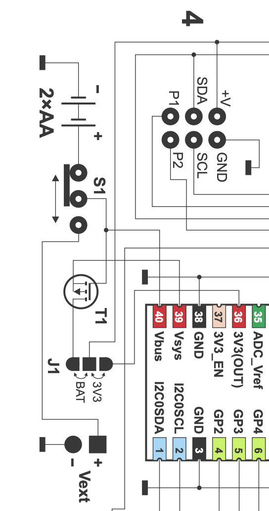
I used two photos of the actual board to check when something wasn’t clear. One such puzzle was the 3-pad SMT solder ball jumper. This was shown on the schematic and on the fully assembled PCB, but it was not in the Circuit Maker design files. I assumed that the schematics and photos were the truth, and the PCB artwork was a previous revision. There is a chance that I got it backwards, but it’s an easy to fix if so. Adding the missing jumper took a bit of guesswork regarding the new and adjusted traces, because they were hard to see and/or underneath parts in the photo. This redrawn design may differ slightly in appearance but not in functionality.

DRC checks took a little more iterating than usual, and at one point I did something to break the edge cuts layer. The irregular features on this PCB didn’t help matters, but I eventually got everything cleaned up.

I had some trouble sometimes assigning nets to the traces. If I was lucky, putting the KiCad footprint on top of the traces assigned them their net names. Other times, I had traces which I had to manually assign to a net. This operation seemed to work sporatically, and I couldn’t figure out why. I was missing a mode that I remember from another decade in a PCB tool, maybe PCAD?, where you would first click on a net. Then you just clicked on any number of other items to stitch them into the net. In KiCad it is not that simple, but understandable given the less-frequent need for this functionality.

You may notice the thru hole leads on the 3D render are way too long. Manufacturers provide 3D files describing the part as they are shipped, which reasonably includes the long leads. They are only trimmed at installation. The virtual technician inside KiCad’s 3D viewer works at inhuman speeds, but has had limited training. She can install or remove all through hold or SMT parts on the board, in the blink of an eye. She can reposition eight lamps and change the background color in mere seconds. These are tasks that would occupy a human technician for hours. But she doesn’t know how to trim the leads off of thru hole parts. Maybe that will come in future versions.

Project Libraries

I like to extract all symbols, part footprints, and 3D files into separate project libraries when the design wraps up. KiCad experts will point out that for several versions now this is not necessary. All (or most) of this information is now stored in the design files, alghouth with one exception — the 3D files. Even so, I still feel safer making these project libraries, probably because I understand the process.

KiCad can now do this with a built-in function. See the Export -> Symbols to New Library and Export -> Footprints to New Library in the schematic and PCB editors, respectively. These actions give you the option to additionally change all references in the design to use this new library. This didn’t work completely for me, for reasons unclear. Eventually I just manually edited the sch and pcb file and fixed the library names with a search and replace operation.

Hint: When configuring project libraries in KiCad, I always give them a nickname that begins with a dot. For example, .badge24 or .stumbler. This always puts project libraries at the top of the long list of libraries, and it makes it easier to do manual search and replaces in the design files if needed.

What about 3D files, you say? That isn’t built into KiCad, but have no fear. [Mitja Nemec] has you covered with the Archive 3D Models KiCad plugin. It was trivial to activate and use in KiCad’s Plugin and Content Manager.

All Done

In the end, the design passed all DRCs, and I could run Update PCB from Schematic... without errors. I went out on a limb and immediately placed an order for five PCBs, hoping I hadn’t overlooked something. But it’s only US$9.00 risk. They are on the way from China as I type this.

All the files can be found in this GitHub repo. If you find any errors, raise an issue there. I have not done this procedure for any of the SAO petals, but when I do, I will place a link in the repository.
Schematics showing jumper

Experimenting With MicroPython On The Bus Pirate 5

I recently got one of the new RP2040-based Bus Pirate 5 (BP5), a multi-purpose interface debugging and testing tool. Scanning the various such tools in my toolbox already: an Analog Discovery 2, a new Glasgow Interface Explorer, and a couple of pyboards, I realized they all had a Python or MicroPython user interface. A few people on the BP5 forums had tossed around the idea of MicroPython, and it just so happened that I was experimenting with building beta versions of MicroPython for a RP2350 board at the time. Naturally, I started wondering, “just how hard can it be to get MicroPython running on the BP5?”

The Lazy Approach

Rather than duplicating the BP5 firmware functionality, I decided to ignore it completely and go with existing MicroPython capabilities. I planned to just make a simple set of board definition files — perhaps Board Support Package (BSP) is a better term? I’ve done this a dozen times before for development and custom boards. Then write a collection of MicroPython modules to conform to the unique aspects in the BP5 hardware. As user [torwag] over on the Bus Pirate forums said back in March:

Micropython comes already with some modules and enough functions to get some stuff out-of-the-box working. E.g. the infamous version of “hello world” for microcontrollers aka led-blinking.

Continue reading “Experimenting With MicroPython On The Bus Pirate 5”

RP2040 Boot Loader Is A Worm

[Hunter Adams] has written a secondary bootloader for the RP2040 that uses an IR link and can be extended to behave like a polite worm virus. This allows the easy updating of a large cluster of co-located RP2040-based controllers. This could be handy in applications like swarm robotics or virtual cattle fencing. The project he demonstrates in the two videos ( below the break ) uses a pair of IR transmitters/receivers. But he purposely wrote the boot loader to be independent of the serial link, which could be infrared, radio, audio, or just wires.

Not only did [Hunter] make a boot loader, but he documented the entire boot process of the RP2040 chip. Whether or not you need a secondary bootloader, this is an excellent resource for understanding how the RP2040 responds to power cycling and resets. The boot loader code is available at his GitHub repository.

You may recall that [Hunter] is the lecturer of Cornell University’s Designing with Microcontroller classes, whom we’ve mentioned before. We’ve also covered some of his students’ projects as well, like these air drums and this CoreXY pen plotter.

Continue reading “RP2040 Boot Loader Is A Worm”

Arctic Adventures With A Data General Nova II — The Equipment

As I walked into the huge high bay that was to be my part-time office for the next couple of years, I was greeted by all manner of abandoned equipment haphazardly scattered around the room. As I later learned, this place was a graveyard for old research projects, cast aside to be later gutted for parts or forgotten entirely. This was my first day on the job as a co-op student at the Georgia Tech Engineering Experiment Station (EES, since renamed to GTRI). The engineer who gave me the orientation tour that day pointed to a dusty electronic rack in one corner of the room. Steve said my job would be to bring that old minicomputer back to life. Once running, I would operate it as directed by the radar researchers and scientists in our group. Thus began a journey that resulted in an Arctic adventure two years later.

The Equipment

The computer in question was a Data General (DG) mini computer. DG was founded by former Digital Equipment Corporation (DEC) employees in the 1960s. They introduced the 16-bit Nova computer in 1969 to compete with DEC’s PDP-8. I was gawking at a fully-equipped Nova 2 system which had been introduced in 1975. This machine and its accessories occupied two full racks, with an adjacent printer and a table with a terminal and pen plotter. There was little to no documentation. Just to turn it on, I had to pester engineers until I found one who could teach me the necessary front-panel switch incantation to boot it up. Continue reading “Arctic Adventures With A Data General Nova II — The Equipment”

Simon Says With An RP2040

The team of [Michael] and [Chimdi] from Cornell’s Designing with Microcontrollers (ECE 4760) Fall 2023 session designed a version of Simon Says on an RP2040 which they call Pico Says. It uses UDP packets over WiFi to communicate between the players, and supports VGA graphics for output. Each player’s hardware consists of a Pico W module plus a control panel containing the four LEDs and buttons ( red, green, yellow, and blue ) plus send and reset buttons.

For purposes of this lab, the modules were build on a solderless breadboard and used perfboard for the control panels. They weren’t entirely happy with their choice of UDP because they experienced frequent datagram dropouts in the noisy environment of the microcontroller lab. They also planned to implement sound effects, but ran out of time after spending too much time on the WiFi implementation, and had to drop that feature. In the end, however, they wrapped up their project and demonstrated a working game. We can only speculate whether this bonus lesson in resource management was intended by [Dr. Hunter Adams] or not.

Two ECE 4760 course references are highlighted in the write-up that helped them jump-start the project: the UDP and VGA examples for the Pico. These are good links to put in your RP2020 toolbox for future projects, in addition to the ECE 4760 course home page itself. We’ve covered several of these projects recently, as well as the curriculum switch from the Microchip PIC32MX-based Microstick II to the RP2040 last Spring.

Continue reading “Simon Says With An RP2040”

Vectorscope KiCad Redrawing Project

When I saw this year’s Supercon Vectorscope badge, I decided that I had to build one for myself. Since I couldn’t attend in-person, I immediately got the PCBs and parts on order. Noting that the GitHub repository only had the KiCad PCB file and not the associated schematics and project file, I assumed this was because everyone was in a rush during the days leading up to Supercon weekend. I later learned, however, that there really wasn’t a KiCad project — the original design was done in Circuit Maker and the PCB was converted into KiCad. I thought, “how hard can this be?” and decided to try my hand at completing the KiCad project.

Fortunately I didn’t have to start from scratch. The PCB schematics were provided, although only as image files. They are nicely laid out and fortunately don’t suffer the scourge of many schematics these days — “visual net lists” that are neither good schematics nor useful net lists. To the contrary, these schematics, while having a slightly unorthodox top to bottom flow, are an example of good schematic design. Continue reading “Vectorscope KiCad Redrawing Project”

Nixie Tube RPN Calculator Project

If you like Nixie tubes and/or DIY calculators, checkout this interesting talk from the HP Handheld Conference in Orlando last month by [Eric Smith] from Brouhaha and [John Doran] from Time Fracture. For 20-some years, [Eric] and the late [Richard Ottosen] have been incrementally developing various DIY calculators — this paper from the 2005 HHC conference is an excellent overview of the early project. [John] got one of those early DIY calculators and set about modifying it to use Nixie tubes. However, he got distracted by other things and set it aside — until reviving it earlier this year and enlisting [Eric]’s aid.

This presentation goes over the hardware aspects of the design. Unlike the earlier PIC-based DIY calculators, they decided to use a WCH RISC-V processor this time around. The calculator’s architecture is intentionally modular, with the display and keyboard housed in completely separate enclosures communicating by a serial interface. If the bulkiness alone doesn’t exclude it from being pocket-sized, the 170 VDC power supply and 1/2 W per digit power consumption certainly does. This modularity does lend itself to DIYers replacing the display, or the keyboard, with something different. [Eric] wants to build a mechanical flip-digit display for his unit. As for the software, [Eric] reviews the firmware approach and some future upgrades, such as making it programmable and emulating other flavors of HP calculators.

If you’re embarking on a similar project yourself, check out this talk and take notes — there are a lot of interesting tidbits on using Nixie tubes in the 21st century. If [Eric]’s name sounds familiar, you may know him from the Nonpareil calculator software used on many emulators and DIY calculator projects, one of which we covered some years ago. [John] is also a long-time tinkerer, and we wrote about his gorgeous D16/M HCMOS computer system back in 2012. Thanks to [Stephen Walters] for sending in the tip.

Continue reading “Nixie Tube RPN Calculator Project”